At a low level, peripherals are anything that interact with a computer to either give it information or send out information. This information can be pretty much anything.
A mouse is a peripheral that inputs the X and Y movement you make, and your computer uses that peripheral to determine where you want your cursor to appear on the screen. Another example would be a temperature sensor that communicates over I2C (pronounced I squared C).
Peripherals can be communicated with via numerous protocols, but we’re only going to cover a few basic types of peripherals and protocols here.
This is the most basic type of peripheral you can attach to a processor. The pins either read the voltage on the line, or they write a voltage to the line. The voltage is digital, meaning it can only be on or off at the specific device’s voltage.
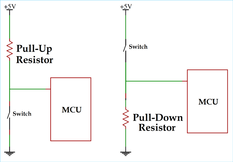
Inputs can have numerous configurations such as high impedance, pull-up, pull-down, or floating. These dictate the standard state of the pin. Pull up means the pin is typically high, while pull down means the pin is typically low. High impedance effectively places an infinite resistor in series, while floating means the pin can do anything.
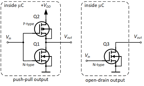
Outputs have numerous configurations as well, such as push-pull, open-drain, and open-collector.
push-pull pins are capable of both sourcing and sinking current to create the desired output due to their structure shown below. Open-Drain pins are only capable of sinking current and rely on external pullups to set the voltage on the pin. This is shown below as well.
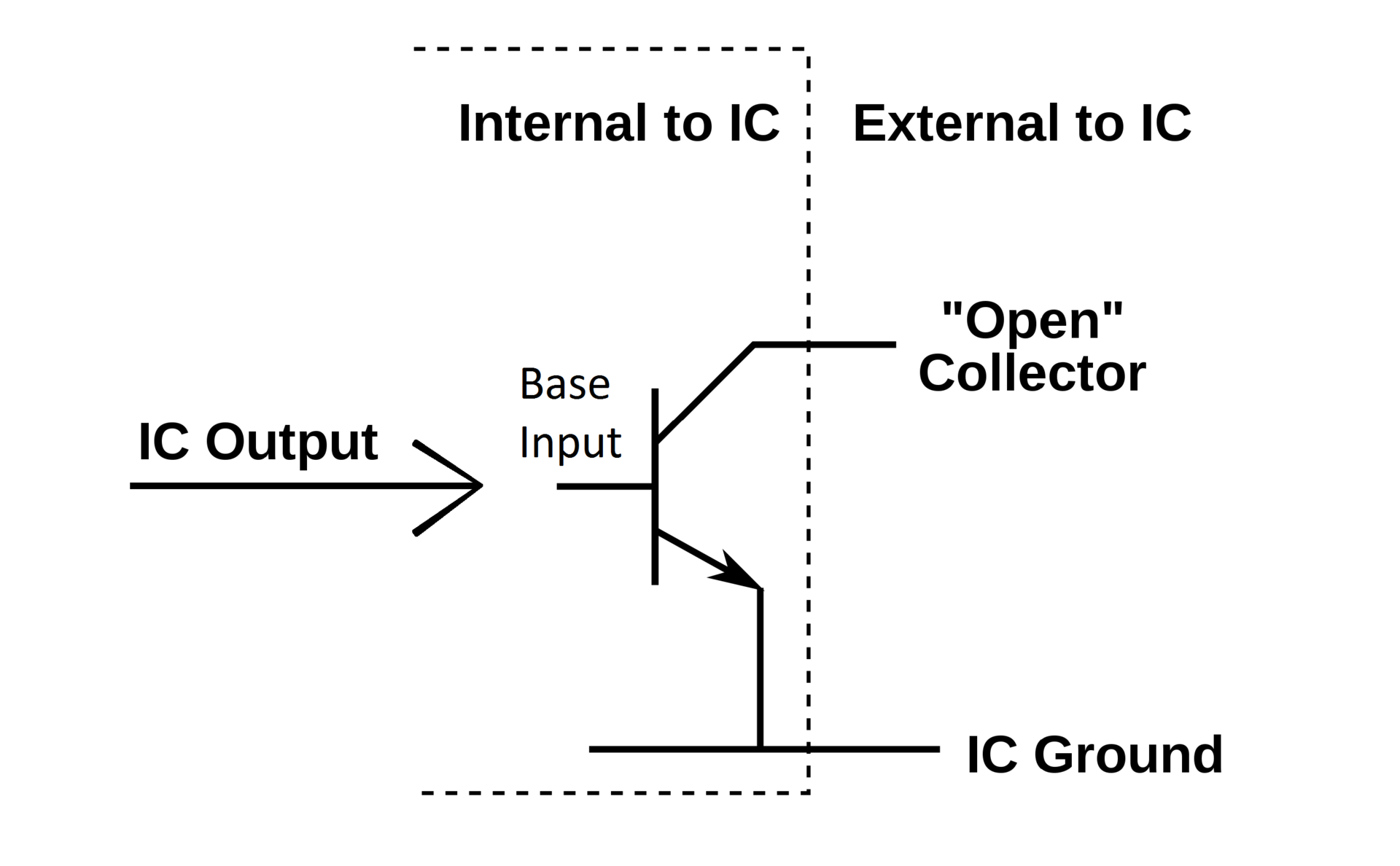
Open Collector is effectively the same thing as open drain except it uses a BJT rather than a FET, as shown below.
Analog to Digital Converters(ADCs) change a message in the Analog domain into a message that can be processed in the Digital domain. They offer N bits of precision over a voltage range V. If you divide that voltage V by the N bits you receive the resolution of your ADC. Converting Analog signals to the Digital domain is a vital part of modern day signal processing.
Here is an example of what an ADC looks like under the hood at a basic level
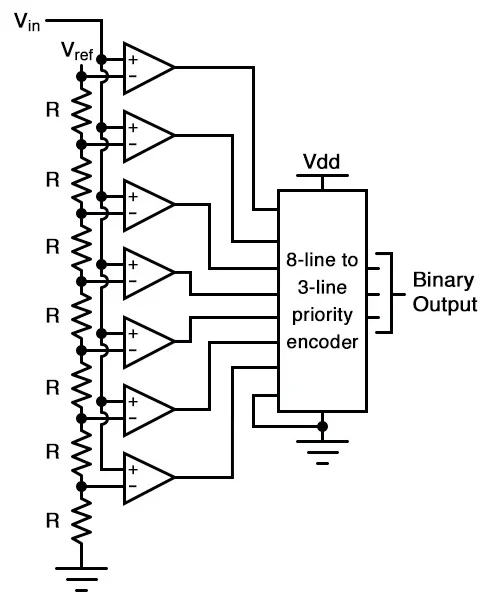 You can see that there are 8 comparators. This means we can measure 8 bits separately. 8 is 2^3 which means by using an encoder we can measure an Analog signal with 8 bits of accuracy, and only need to read three lines.
If Vref in this scenario was +5V, we would have 5 V / 8 Bits therefore each bit would have a resolution of ~625mV.
Digital to Analog Converters(DACs) are the matching pair to your ADCs. Much like we need to convert Analog Signals to Digital Signals, we must do the opposite as well. The music coming from your phone is stored digitally, but eventually the sound played via a speaker must be an Analog waveform.
DACs have the same principle of a reference voltage V, N bits, and a resolution. An Example DAC is shown below.
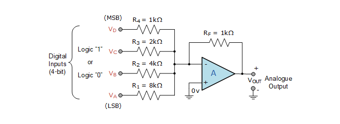 In this example you can see that each bit has a resistor that is double the value of the previous bit in series with the digital line. This means that by setting each individual bit high you can push a proportionate amount of current through the pin, and with the op amp acting inverting amplifier you can effectively translate the digital signals into a known analog signal with a known resolution.
The resolution in this case if the voltage was +5V would be +5V / 4 Bits = 1.25 V. Note the output would be inverted though.
There are resistor to resistor DACs as well that are often utilized. Example below.
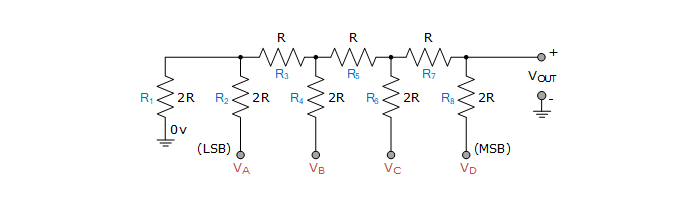 This is useful when you can fit more resistors, and you don’t need the op amp to drive the load.
I2C (I-Squared-C) is a data transfer/protocol rather than a peripheral itself. Think as a method of delivering a message to a peripheral and telling it what you need to do. I2C is a two wire synchronous protocol.
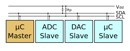 I2C allows a master device (like your microcontroller or CPU) to communicate with numerous slave devices(like sensors, drivers, other microcontrollers, etc.)
The first wire is Serial Clock (SCL). This wire sets the clock speed for the I2C bus, and it’s frequency will depend upon the specific peripheral you’re using. Common frequencies are 100 kHz and 400 kHz.
The second wire is Serial Data (SDA). This wire is used to send all the data between two devices. We’ll go ever an example waveform and how you’d use this protocol below
Each wire requires a pullup resistor because internally the pins are open-collector/open-drain configuration. The value of resistor you chose depends upon the length of the line, and the frequency at which you communicate, but typically 4.7k works fine.
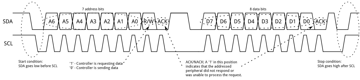
Next up we’ll discuss the message window and how the data is formatted.
 Start Bit
First, SDA is pulled low while SCL remains high. This indicates that the bus is going to be used.
Start Bit
First, SDA is pulled low while SCL remains high. This indicates that the bus is going to be used.
Address This indicates the address to which the master will be writing. This is an 7 Bit message that is sent Most Significant Bit(MSB) First. The address of the slave device is given in the device’s data sheet.
Read/Write Bit The 8th bit of the message determines whether the master will be reading or writing from the slave device specified at the address. 0 is a write operation, 1 is a read operation.
Acknowledge To show that the slave device successfully received the message, an acknowledgement(ACK) bit is sent on SCL. This is the 9th Bit.
If ACK is low that means the slave successfully received the message, and if it is high then the transfer failed, the communication ends, and the master is free to react to that failure.
Data Frame Assuming the ACK bit was low, then the master will continue creating a constant clock signal on SCK until it has received or written everything it needs. Master or Slave will continue reading/writing until the master determines that the transfer is done.
Stop Condition The transfer stops when the Master pulls SDA high while SCL is already high. You don’t modify SDA while SCL is high unless you intend to stop the transfer.
The final communication protocol that we’ll discuss is SPI. At a basic level SPI is just a clock, two data lines, and on and off switches for your slaves.
Here is an example configuration with three slave devices.
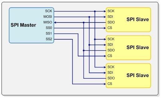 SCK is the clock for the interface. MOSI is Master Out Slave In. MISO is Master In Slave Out, and lastly SS# means slave select. Slave Select enables the particular peripheral device your master is communicating, and then the data transfer begins.
There is no exact configuration for the data in SPI, and there are actually four different sampling times for the data depending upon the specific peripheral. The sampling configuration determines at what point in the waveform the data will be sampled for the device’s usage.
These mode definitions are determines by the value of CPOL and CPHA flags. The Wiki for SPI has information on this.
Overall SPI is a simpler protocol (minus the four different configurations) that allows for very fast communication (~x10 faster than I2C).
There are a million more types of protocols out there, and guess what, there is no point in learning them all right now. If you’re designing automotive controls your going to need to learn how to use a CANBus. If you’re making a keyboard you’re going to need to learn the USB protocol. In automation you’re going to need to learn RS-Insert Three Numbers Here protocol.
This just shows you a few of the common ones. Find parts that serve your purpose, and if they require a specific protocol learn it :)